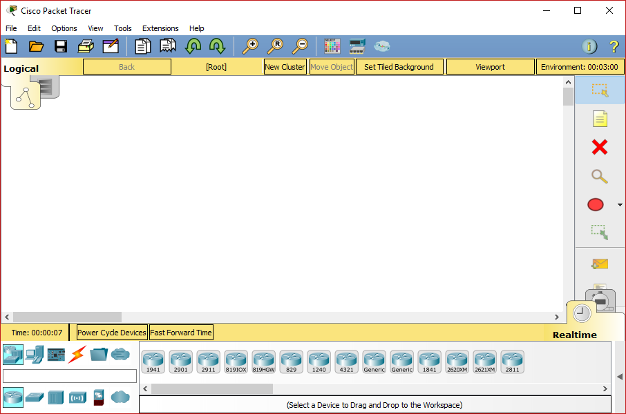
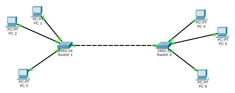
To perform the CCNA hands-on lab exercises, first, you need to download Cisco Packet Tracer. In the previous post, we explained the process how to download Cisco Packet Tracer. Click here to know how to download Cisco Packet Tracer. Once it is downloaded, install it using the default selections. After the installation, you can create a network topology to perform the hands-on lab exercises. In this post, we will discuss how to create a network topology using Cisco Packet Tracer.
Create a Network Topology
You can easily create a network topology using Cisco Packet Tracer. In the following sections, we are going to explain how to create a network topology that will contain four PCs, two switches, and two routers.
Cisco Packet Tracer, created by Cisco Systems, is a simulation tool that allows us to logically create a network topology without even implementing it physically. It can be used to understand all the basic concepts of computer networking, mainly CCNA.
Adding PCs in Cisco Packet Tracer
To add PCs in Cisco Packet Tracer, you need to perform the following steps:
- In the Cisco Packet Tracer console, click on the PC icon, click Generic, and then click in the logical view area to add a Generic PC.
- Repeat the same step to add three more Generic PCs in the logical view area, as shown in the following figure.
- Packet Tracer 5.1 is the latest version of Cisco's simulation software. The main objective of Packet Tracer is to serve as a support tool for the Cisco Academy. This tool is extremely useful for both students and teachers.
- Cisco Packet Tracer (CPT) is a powerful network simulator program developed by Cisco. With this simulator program, you can prepare for Cisco exams by building complex networks and improve your network knowledge. The purpose of using this software is to prepare for Cisco CCNA or CCNP exams.
- Dont have packet tracer to test. But Looks like you have Routing issue, make sure ip routing enabled. And traceroute is good command for learning and tell you where it was dropped. So you can investigate from that point have routing in place.
- Cisco Packet Tracer is a network-capable application. It has a multiuser peer-to-peer mode to enable the collaborative construction of digital networks on the real systems. This multiuser feature facilitates incredible competitive interactions and collaborations. People can use it for social interactions, gaming, and learning.
Adding Switches in Cisco Packet Tracer
- To add a switch in Cisco Packet Tracer, click the Switch icon, select a switch type, such as 2960, and then add the selected switch in the logical view area.
- Repeat the same step to add one more switch.
Adding Routers in Cisco Packet Tracer
- To add a router in Cisco Packet Tracer, click the Router icon, select a router type, such as 2811, and then add the selected router in the logical view area.
- Repeat the same step to add one more router.
Note: Different types of router series provide different types of features and limitations.
Understanding Connection Types in Cisco Packet Tracer
To connect devices in Cisco Packet Tracer, first, you need to understand the various types of cables (connections) used to connect network devices. Some of the common types of cables are:
- Straight-through: Used to connect different types of devices (devices that use different wiring standards), such as Router-to-Switch and Switch-to-PC.
- Cross-over: Used to connect same types of devices, such as router-to-router, PC-to-PC, and switch-to-switch.
- Serial DCE: Used to connect router-to-router in a WAN network.
- Console: Used to take console (using hyper terminal) of a router on a PC.
To see the various types of connections, click the Connection icon. Spend some time to understand the connections. Once you are familiar with the types of connections, connect the devices to create the network topology.
The following figure displays the various types of connections used to connect devices.
Since we have chosen the modular router (that allows you to modify the number of interfaces), you may need to customize the interfaces before it can be used to connect other network devices. To do this, double-click Router0, on the Router0 properties dialog box, click the Power button to power off Router0.
The following figure displays how to add a module in a router using Cisco Packet Tracer.
Now, open the Router1 properties dialog box, add the same module to Router1 also, and then close the Router1 properties dialog box.
Connecting Devices in Cisco Packet Tracer
- To connect devices in Cisco Packet Tracer, click the connection type icon, and select an appropriate cable. For example, to connect PC0 to Switch0, select the straight-through cable, click on PC0, select the FastEthernet0 interface.
- Next, click on Switch0, and then select the FastEthernet0/1 interface. The following figure displays how to connect a PC to a switch in Cisco Packet Tracer.
- Now, add PC1 to Switch0 using the FastEthernet0/2 interface. Also, add PC2 and PC3 to the FastEthernet0/1 and FastEthernet0/2 interfaces of Switch1, respectively.
- If you have connected a wrong device to a wrong interface, you can use the Delete option to delete a connection or device. The following figure displays how to use the Delete option to delete a device or connection in Cisco Packet Tracer.
- Once, you have connected all the PCs to switches, now, connect Switch0 to Router0, and Switch1 to Router1 using the straight-through cables.
- Select the straight-through cable, click on Switch0, and then select FastEthernet0/3 interface.
- Click Router0 and select the FastEthernet0/0 interface.
- Select again the straight-through cable, click on Switch1, and select FastEthernet0/3 interface.
- Next, click Router1 and then select the FastEthernet0/0 interface.
The following figure displays how to connect routers to switches to create a network topology.
Interconnecting Routers in Cisco Packet Tracer
Now, connect Router0 to Router1 using the serial connection. To do this, you need to perform the following steps:
- Select the Serial DCE cable, click on Router0, and select the Serial1/0 interface.
- Click on Router1 and select the Serial1/0 interface, as shown in the following figure.

In this post, you have learned how to create a network topology in Cisco Packet Tracer. If you wish, you can save the created network topology for the later use. To do this, you need to perform the following steps:
- In Cisco Packet Tracer, click File, and select SaveAs.
- In the File name text box, type a name of the topology, and then click Save.
Also read: Different types of Cisco IOS configuration modes
In this packet tracer lab, we will set up a router for the telnet access. And then use the command prompt on the computer to test our telnet connection.
To telnet the router from our PC we will have to assign an IP address to our PC. After that, we will assign the IP address to the router interface which is connected with that PC.
To make the telnet work perfectly, our PC and router should be on the same network like they are directly connected.

After assigning the IP addresses to both our devices, we have to enable the router for a telnet connection by configuring the VTY lines.
Once we have configured both the devices properly, we can try pinging the router from our PC to check the connectivity. If the router is responding to the ping command we can then establish a telnet connection from our PC’s command prompt.

Once the telnet connection is initiated successfully, we will be prompted with the password to access the router via a telnet connection.
Cisco Packet Tracer Student Download
An important thing, we have to configure the privileged mode password. That’s because it is not possible to access the privileged mode through a telnet connection if the password for our privileged mode is not configured. If you try to view the same by accessing the router via a telnet connection, you will see an error message saying ‘no password set’ when entering into the privileged exec mode without configuring the password.
Cisco Networking Academy Cost
Lab tasks
Cisco Packet Tracer Downloadf
- Set pc0 IP address to 192.168.1.2/24
- Set interface fast Ethernet 0/0 IP address to 192.168.1.1/24
- Set privileged mode password to Cisco
- Enable telnet lines on router
- Test telnet connection via your PC